Personal projects · Arduino
Embedded Projects
Personal projects where every part was mine: the circuit, the firmware, the 3D-printed structure, and whatever broke along the way. A remote-control sailboat, and two generations of a speedcubing timer.
2022–2023 · Personal projects
Arduino (C++) · Python · XBee radios · Soldering · Onshape · 3D printing · Fritzing
These started as projects I wanted to exist, and turned into lessons in everything around the code: making parts that don’t fit together fit, sensors that behave differently in every room, and structures that have to survive being used.
01 · Wireless control · Custom electronics · 2023
Remote-control sailboat
The goal
A sailboat I could control from shore: trim the sail and steer the rudder over a radio link, from either a laptop or a handheld joystick, running on batteries for as long as possible.
- BoatArduino Nano · XBee radio on an Uno shield · SG90 and FS90MR servos · 4×AA pack
- RemotesPython on a laptop with a USB XBee, or an Arduino Uno with a joystick
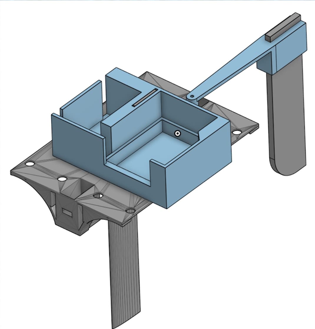
- StructureTwo water bottles · 3D-printed deck, keel, rudder, and electronics holder
A hull I could keep changing
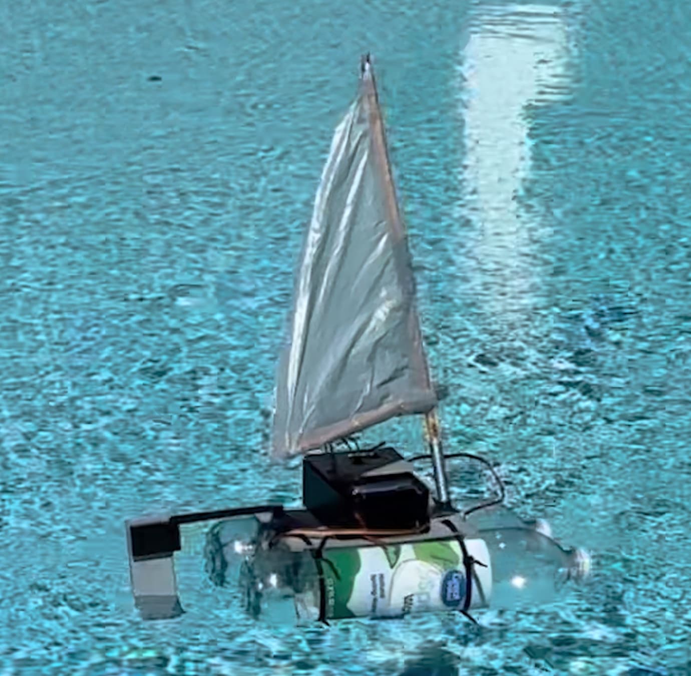
I made the boat a catamaran: two water bottles joined by a 3D-printed deck and keel. Two hulls make it far more stable than one, it moves quickly, and because the printed parts are held on with zip ties, I could redesign any single part without rebuilding the boat.
The problem: the wrong shield
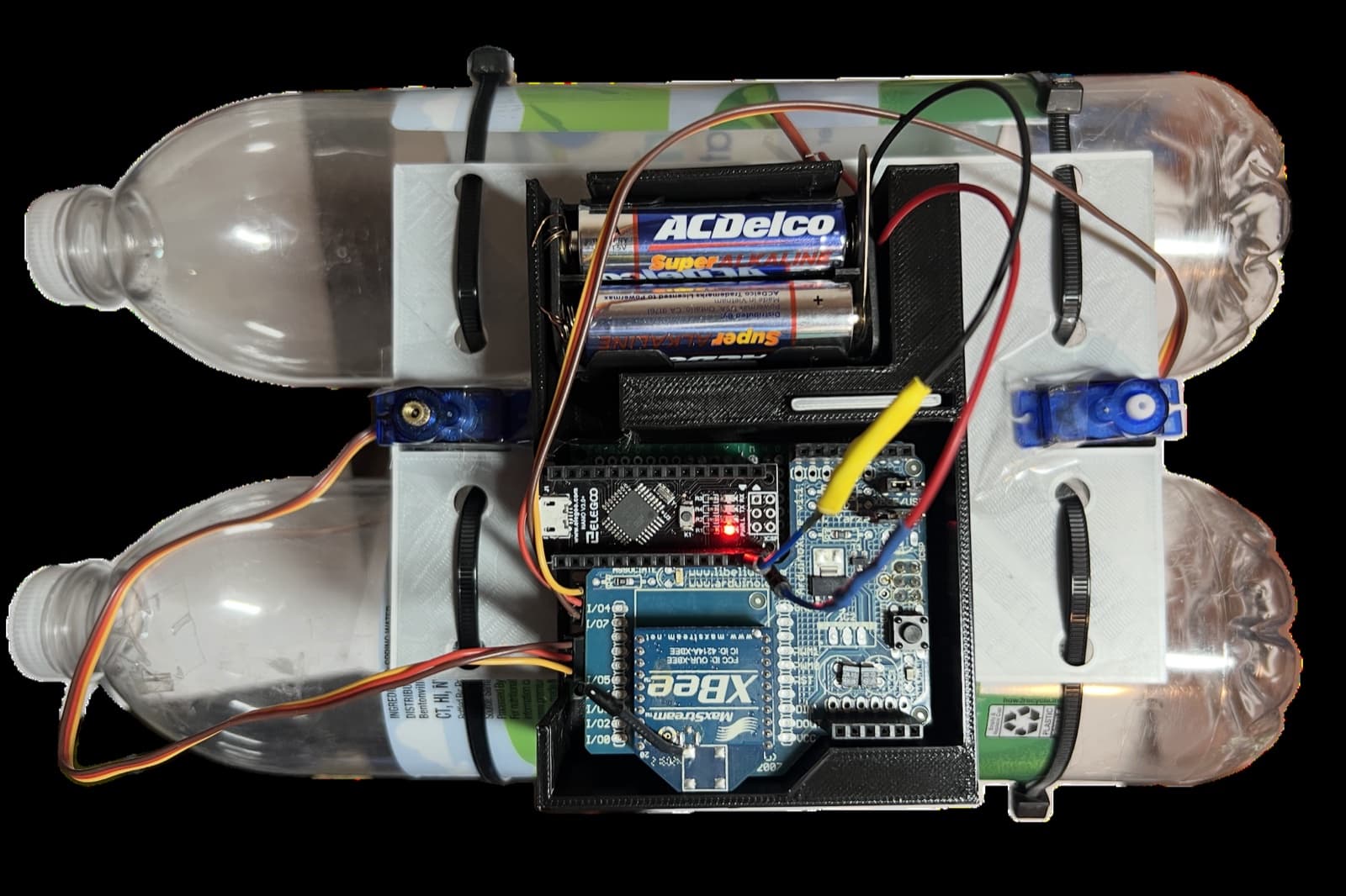
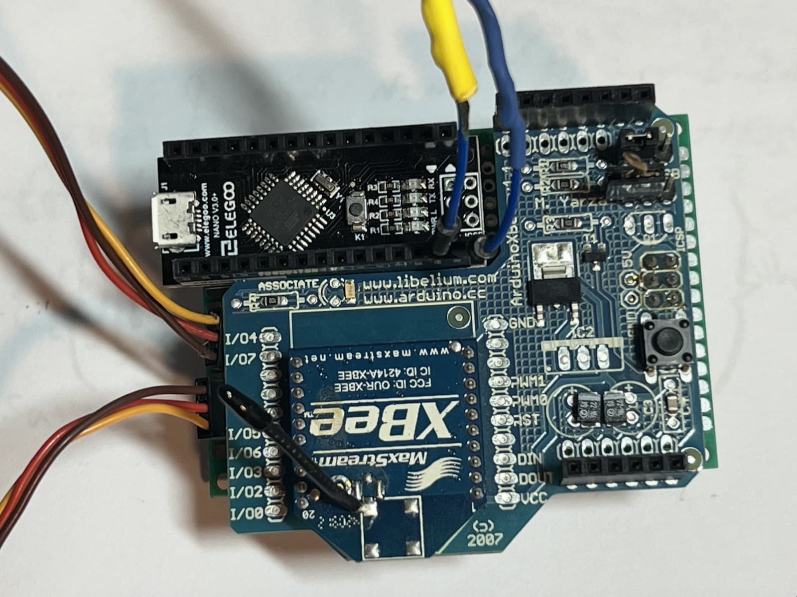
To make the batteries last, the boat runs on an Arduino Nano and micro servos. But the only XBee radio shield I had was made for the Arduino Uno, a much larger board with a different layout, and space on the deck was tight.
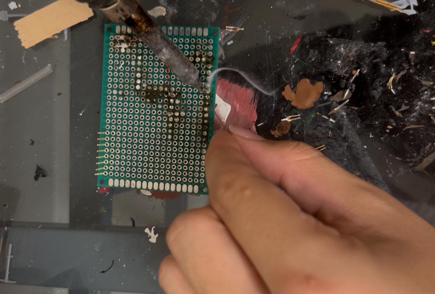
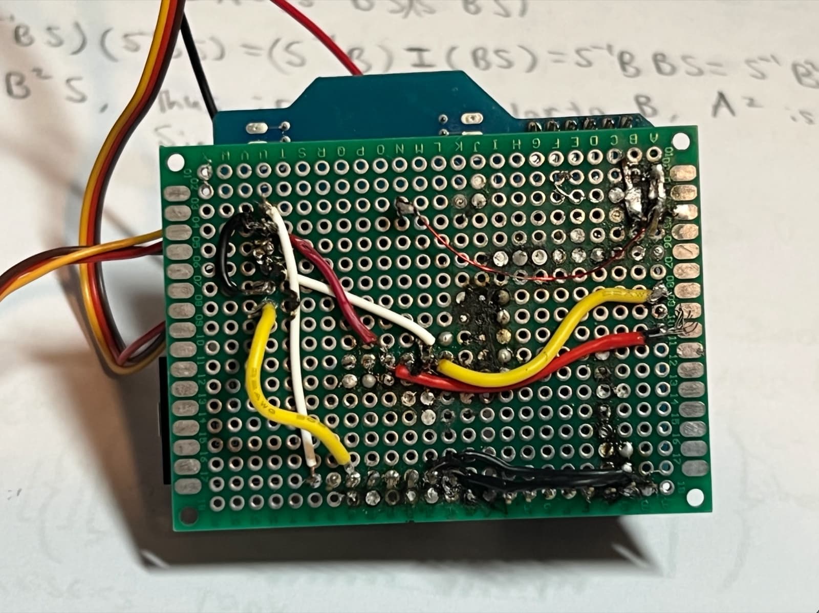
So I made my own adapter: a soldered perfboard that mounts the Nano and the Uno shield together and wires one to the other, laid out to take as little room as possible in the electronics holder.
Firmware and the radio link
Commands travel over the XBee link as single characters at 9600 baud: one pair for sail in and out, one for rudder left and right, and a neutral command for when the stick is released. Both remotes only send when the input changes, and the joystick remote ignores small movements around center, so the radio carries events instead of a constant stream.
The boat does the rest. While a rudder command is active, it steps the rudder one degree every 25 ms until it hears neutral, clamped between 5° and 160° to keep it within its range of motion. The joystick button starts a rescue mode that swings the rudder hard from side to side to work the boat free.
Iterating on the structure
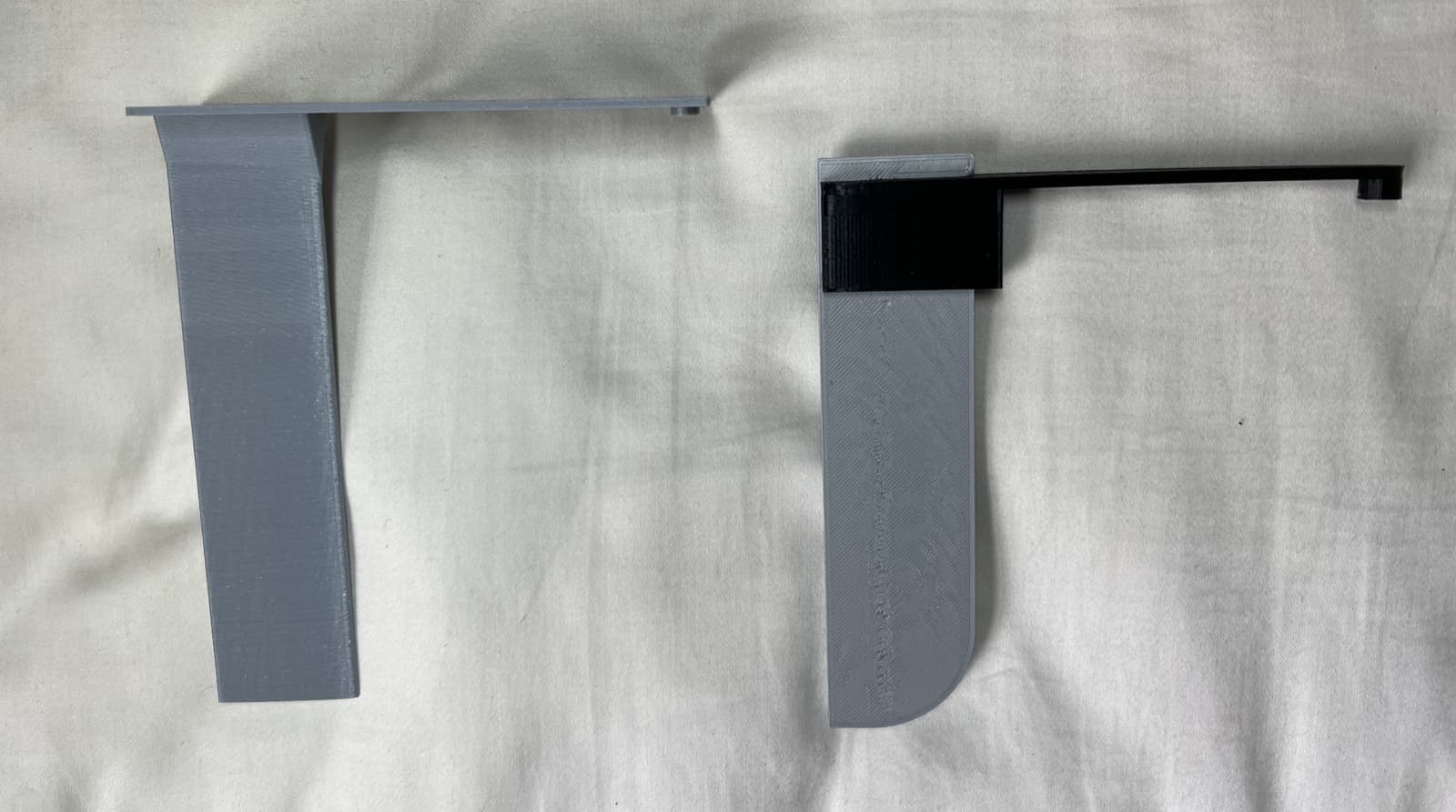
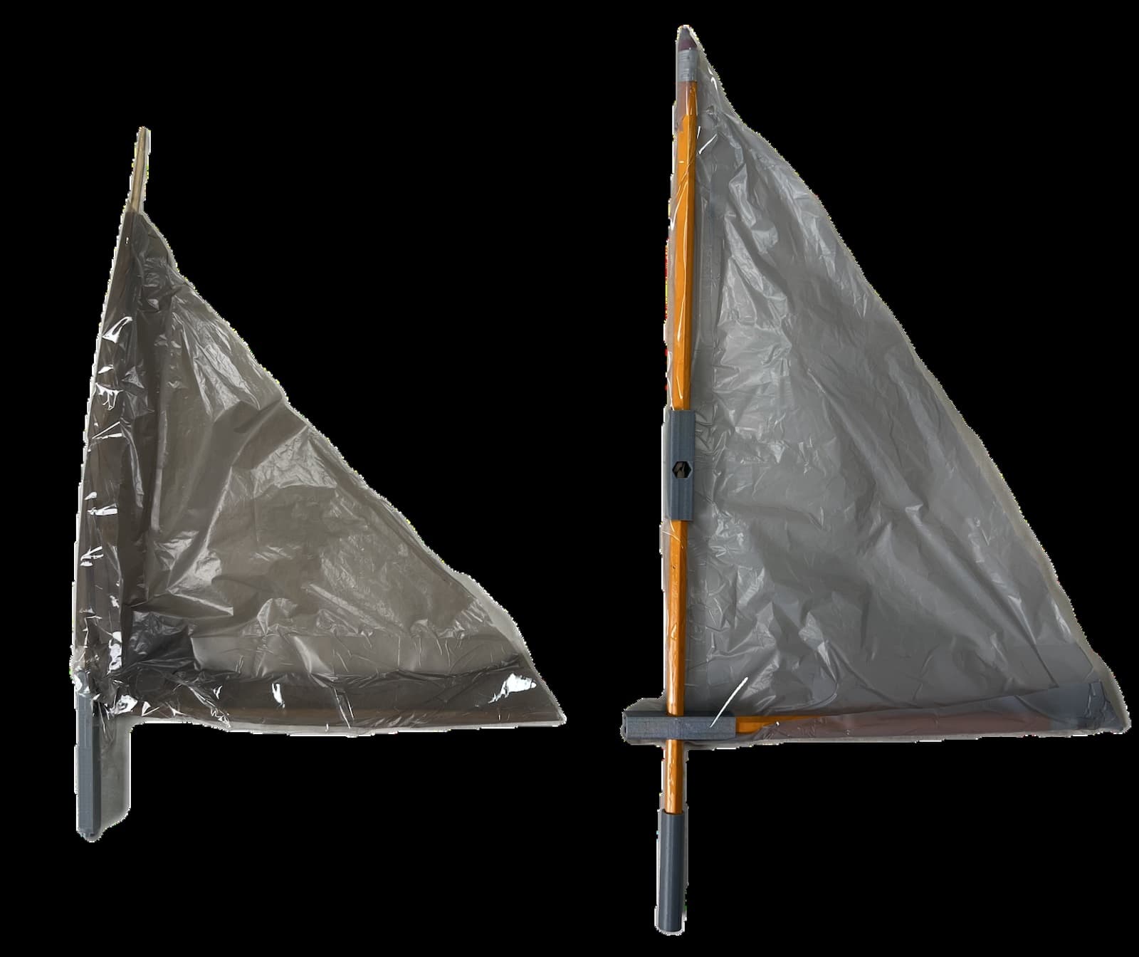
The rudder and sail both went through more than one version. The original sail frame was made from kebab sticks, which are weak and limited how big the sail could be. I rebuilt it from pencils connected by 3D-printed joints, which made it much stiffer and let me fit a larger, more powerful sail.
Result
The boat sails and steers on open water from either remote, on a circuit board I designed around the parts I actually had.
02 · Sensors · Calibration · 2022–2023
Speedcubing timer
The goal
I compete in speedcubing. At official competitions, solves are timed on a Stackmat: you rest both hands on the pads, lift them to start, and put them back to stop, after a 15-second inspection period with penalties for going over. I wanted a practice timer that did all of that, and generated scrambles too.
Version 1: ultrasonic
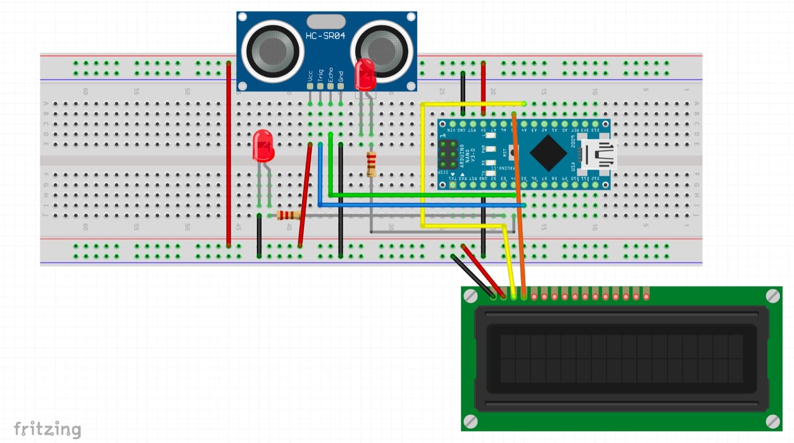
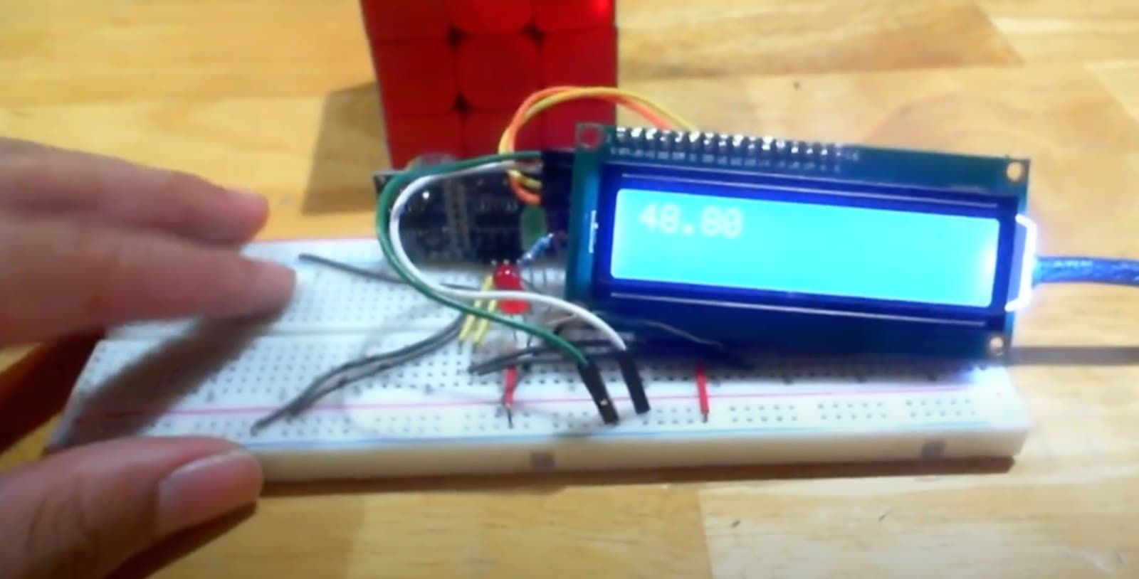
The first version had a single input, an HC-SR04 ultrasonic sensor, which detects the cube instead of hands. It measures how long a sound pulse takes to bounce back and converts that to distance:
distance = echo time · speed of sound / 2
A cube within 4 inches counts as placed. The same sensor steps the timer through its whole sequence: show a scramble, count down inspection, then time the solve, with a red LED while waiting and a green one while timing. Scrambles are 20 random moves that never turn the same face twice in a row, which would cancel out. I used an LCD with an I2C adapter, which needs only two data pins and has its own brightness control.
Version 2: what was wrong, and the fix
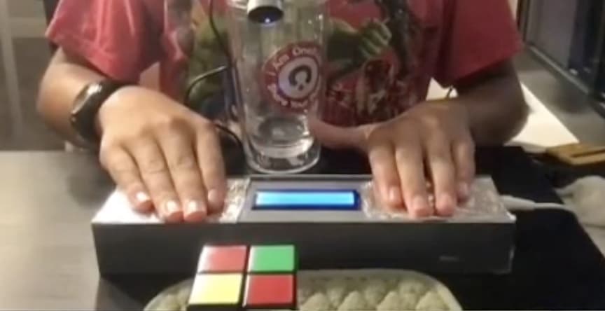
V1 worked, but it didn’t feel like a real timer, since it sensed the cube rather than your hands, and the electronics sat exposed on a breadboard. For V2, I switched to capacitive touch pads, the same way an official Stackmat works. Each pad is aluminum foil glued to the shell and wired through a 1 MΩ resistor, and the Arduino measures how long the pad takes to charge, which rises when a hand is on it.
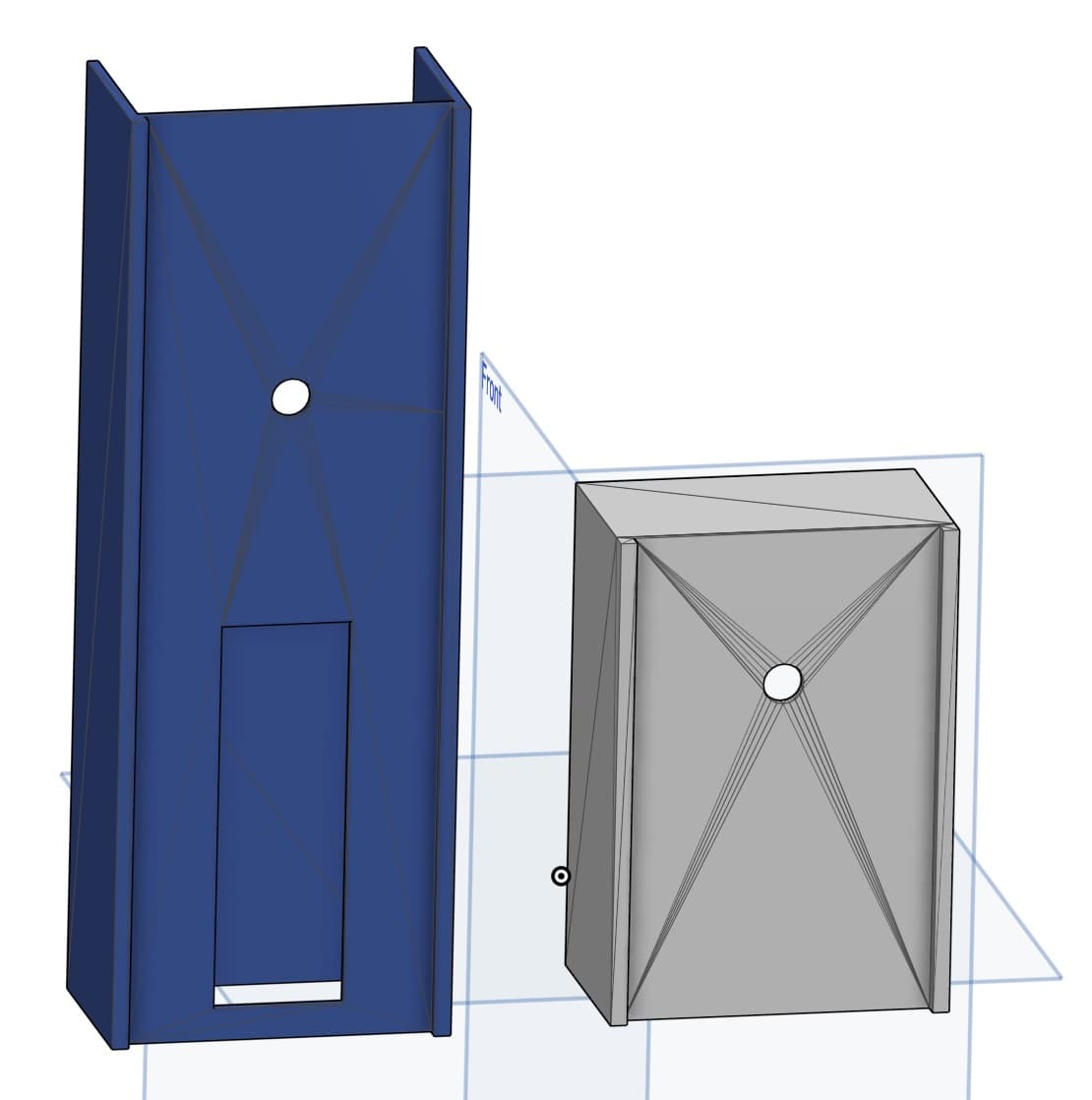
V2 also applies the competition rules itself. It counts down 15 seconds of inspection, adds a +2 penalty if you start late, and records a DNF past 17 seconds, then shows the solve to the millisecond. Everything lives in a 3D-printed shell, printed in two halves and glued, since the whole thing was too big for the printer’s bed.
The hard part: sensors that won’t hold still
The touch pads were the hardest part to get working reliably. A capacitive reading depends on everything around it: humidity, elevation, even the person touching it, so a threshold that works in one setting can fail in another. I wrote a separate calibration program to watch the raw readings, and after a lot of trial and error found the answer was a threshold far lower than I expected, but still high enough that the pads wouldn’t register touches that weren’t there.
Result
A timer that works like the ones at competitions, in a shell sturdy enough to use every day.